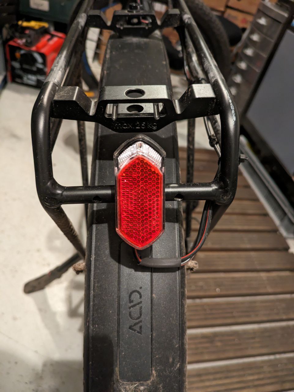
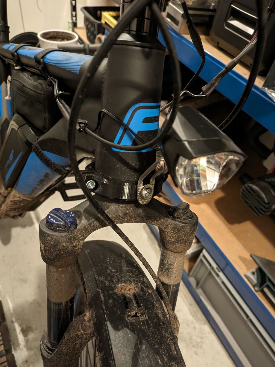
Finally replacing the removable bikelight and mounting a real light. + Update from "Bike Carrier v2"
Bill of Materials
- 1,5mm² Speakercable
- USB 2.0 port for soldering on breadboard
- breadboard
- shrinking tube
- male and female wire connectors
- soldering iron
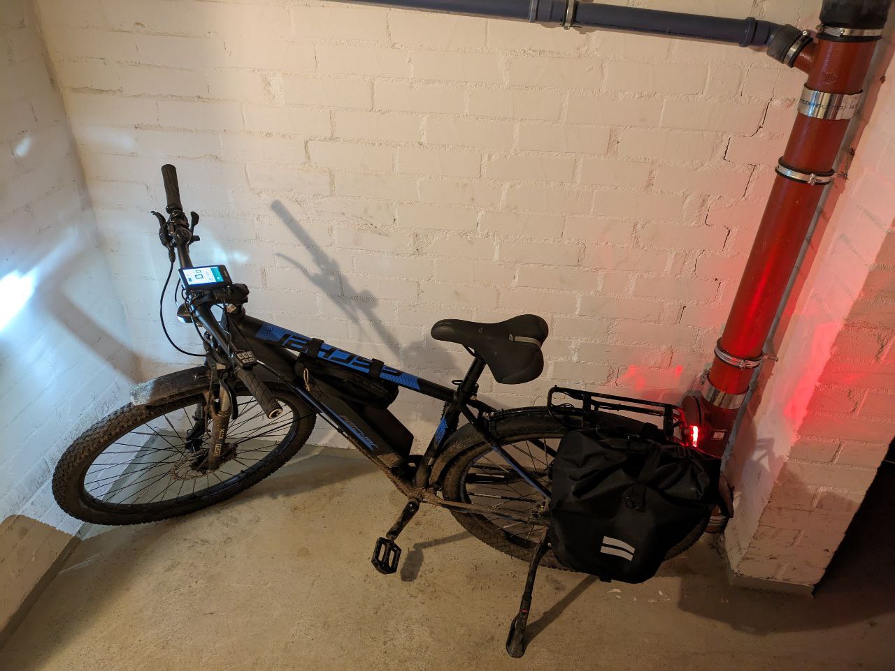
Finished product
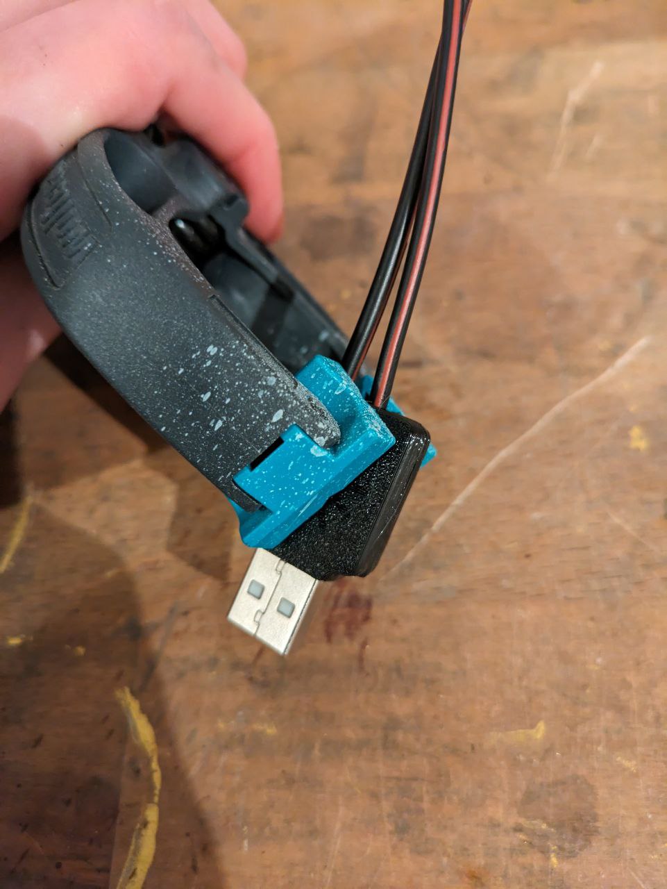
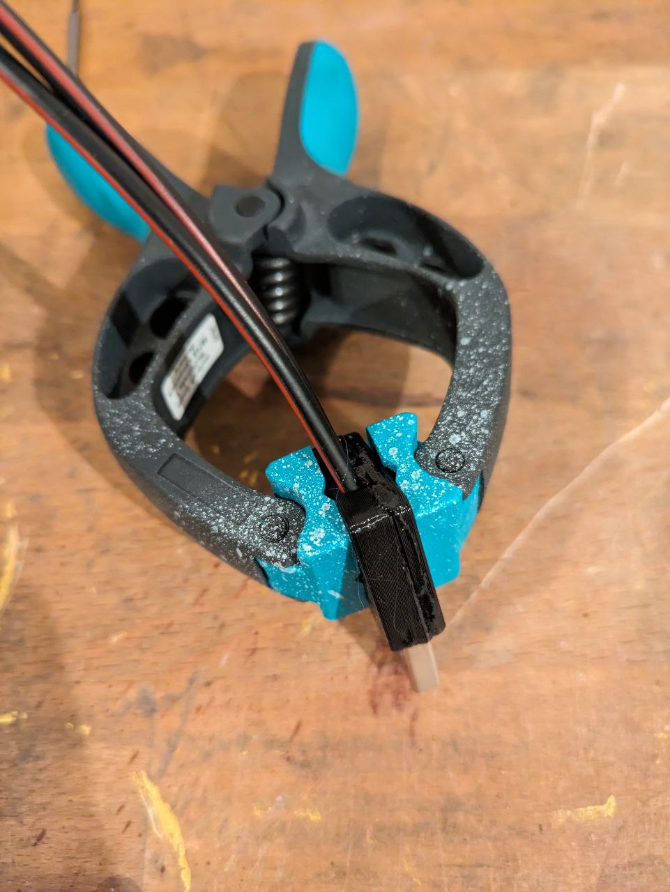
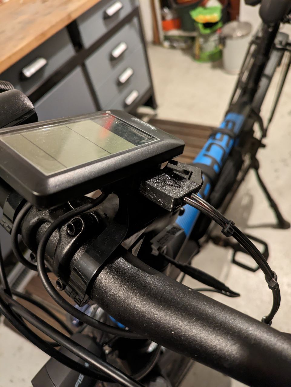
As it´s the unwritten law of the internet to show the finished product first, here it is:
Planning phase
The whole idea about this project is to use my bike battery to power the lights. I wrote the FISCHER support a long time ago with the inquiry if the sell lights that are compatible with my bike. Unfortunately they don´t.
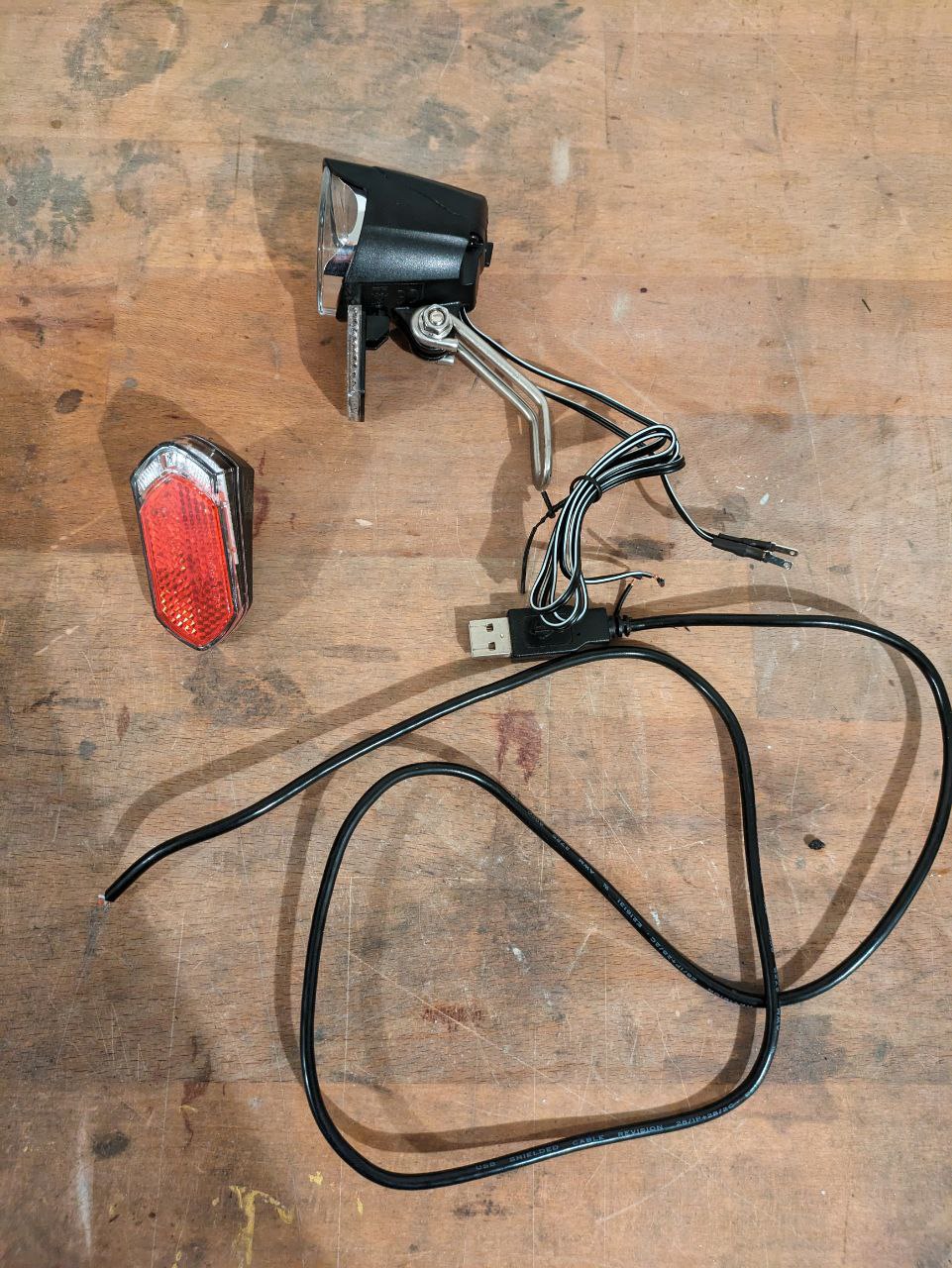
As I have an USB port on my bikes controller, my plan was to buy some lights which intended use was receiving current from a dynamo. The problem with that? Bike dynamos generate 6V @ 3 watt. And my USB port generates 5V @ 1 amp. I got my bench powersupply and hooked up the lights with 5V @ 1 amp - and they worked!
Manufacturing
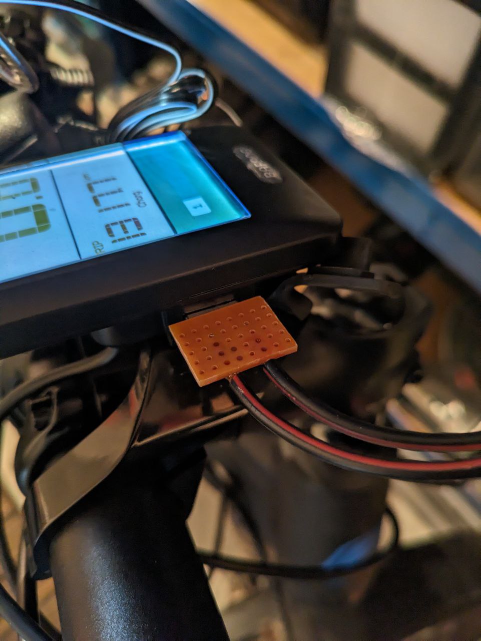
With this new knowledge, my plan was to chop up an old USB cable, clip the data cables and use the two remaining wires.
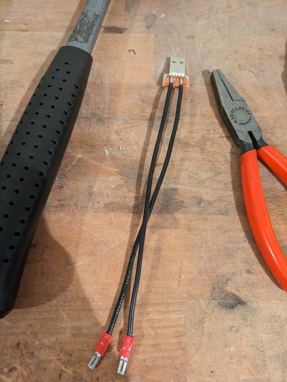
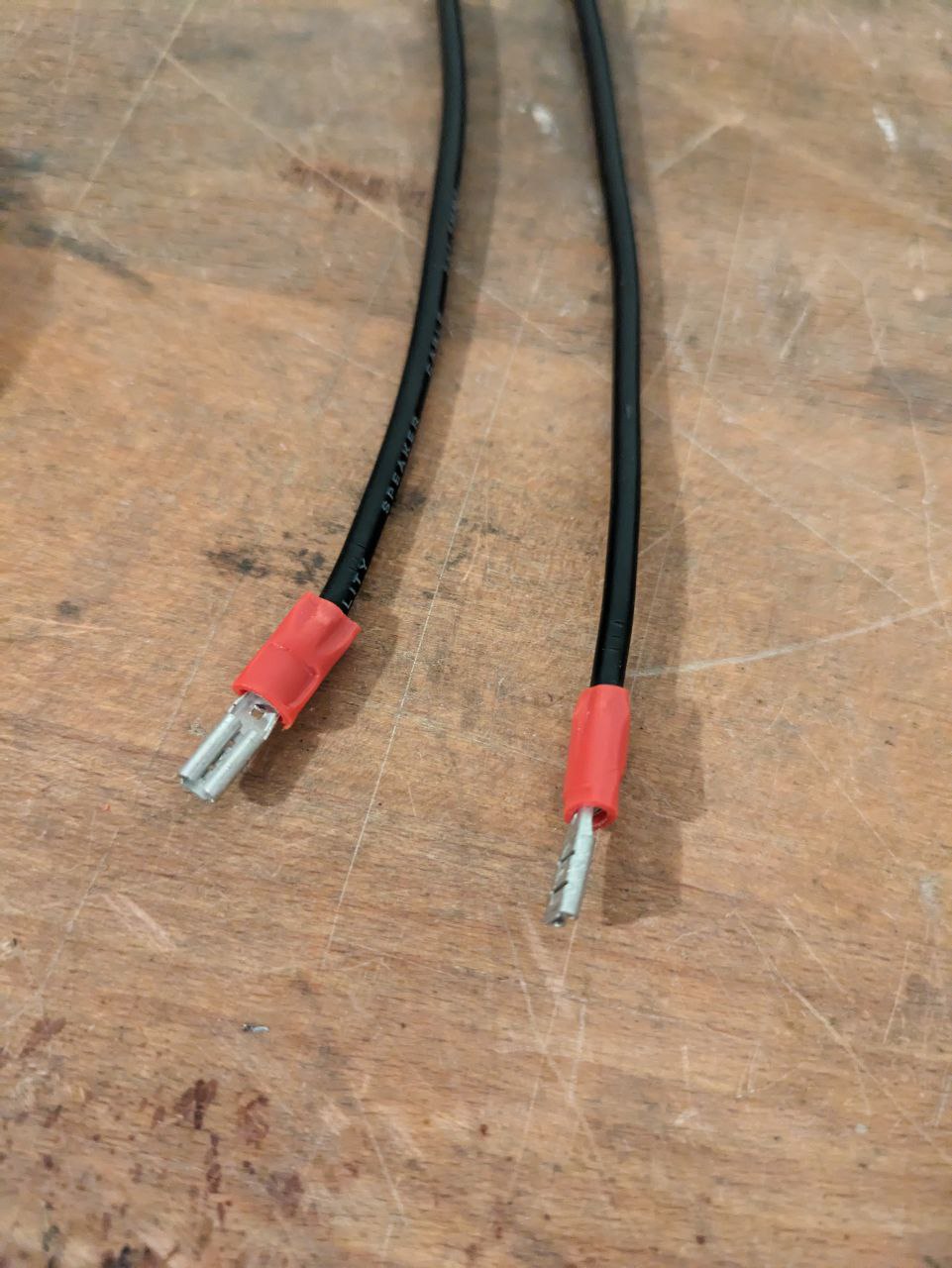
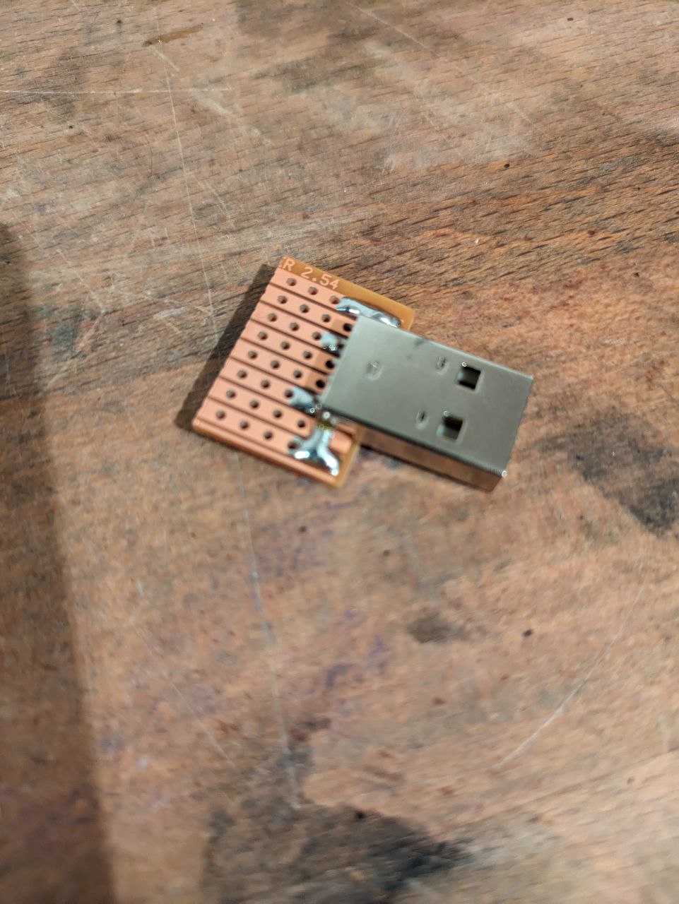
But the wires were way too thin to solder them, so I built my own USB cable with breadboard, 1.5mm² speaker cable an USB port and a soldering iron. Which worked on the first try.
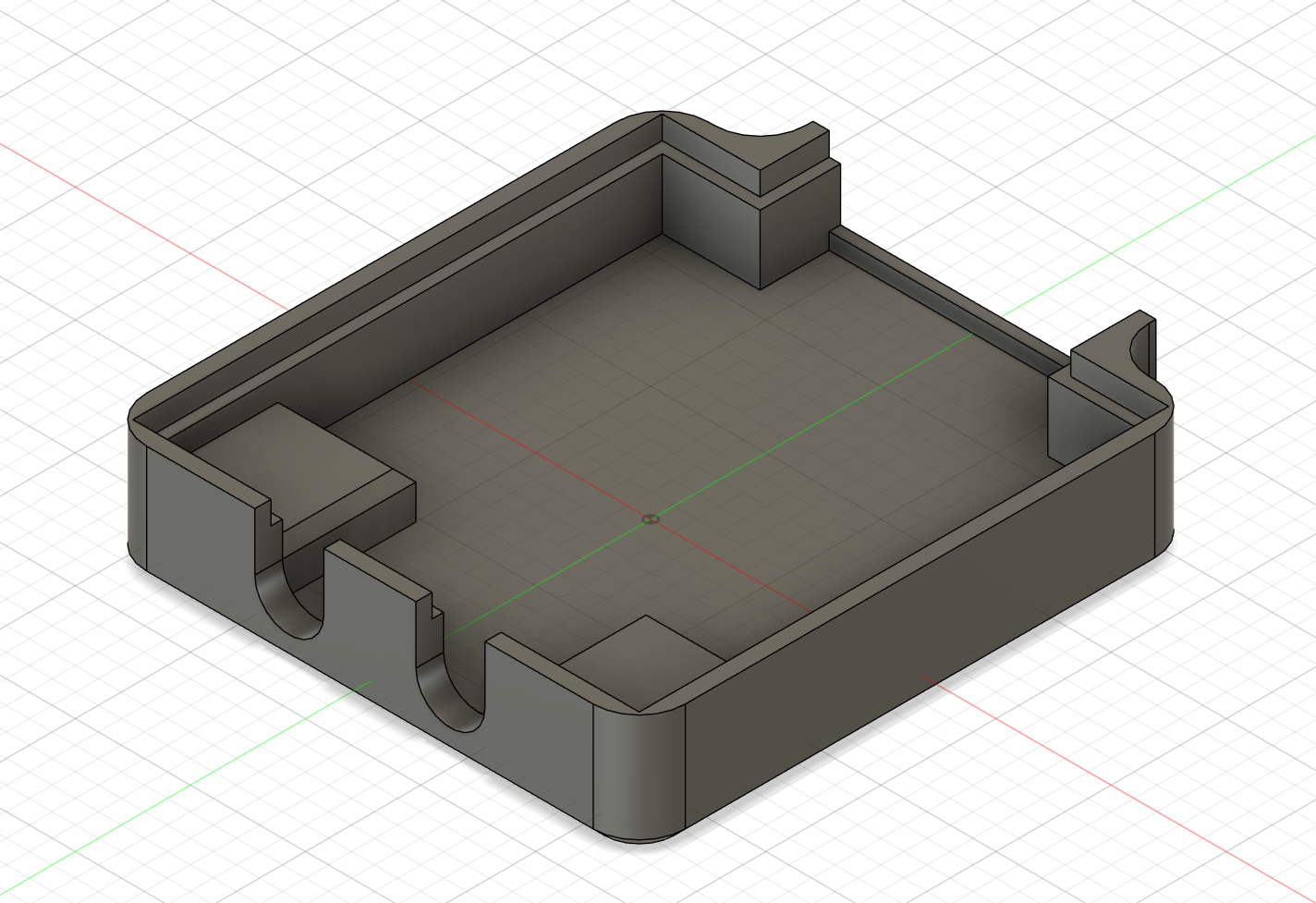
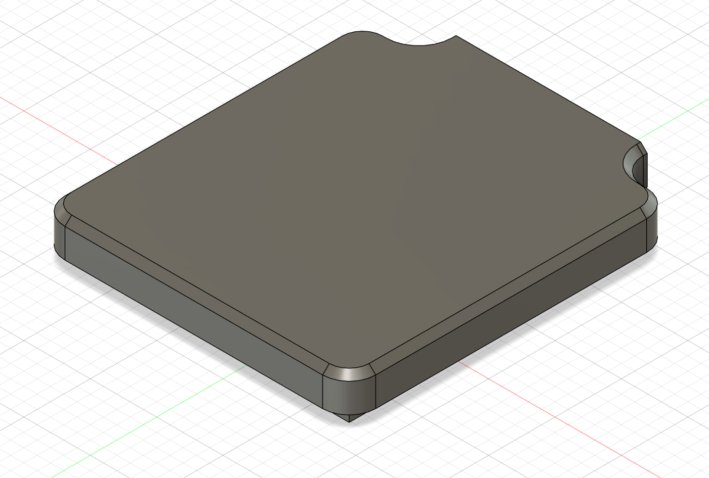
As I have a 3D printer, a housing for the connector had to be made.
Not shown here: I filled in all the cavities with hot glue to protect the electronics from the weather.
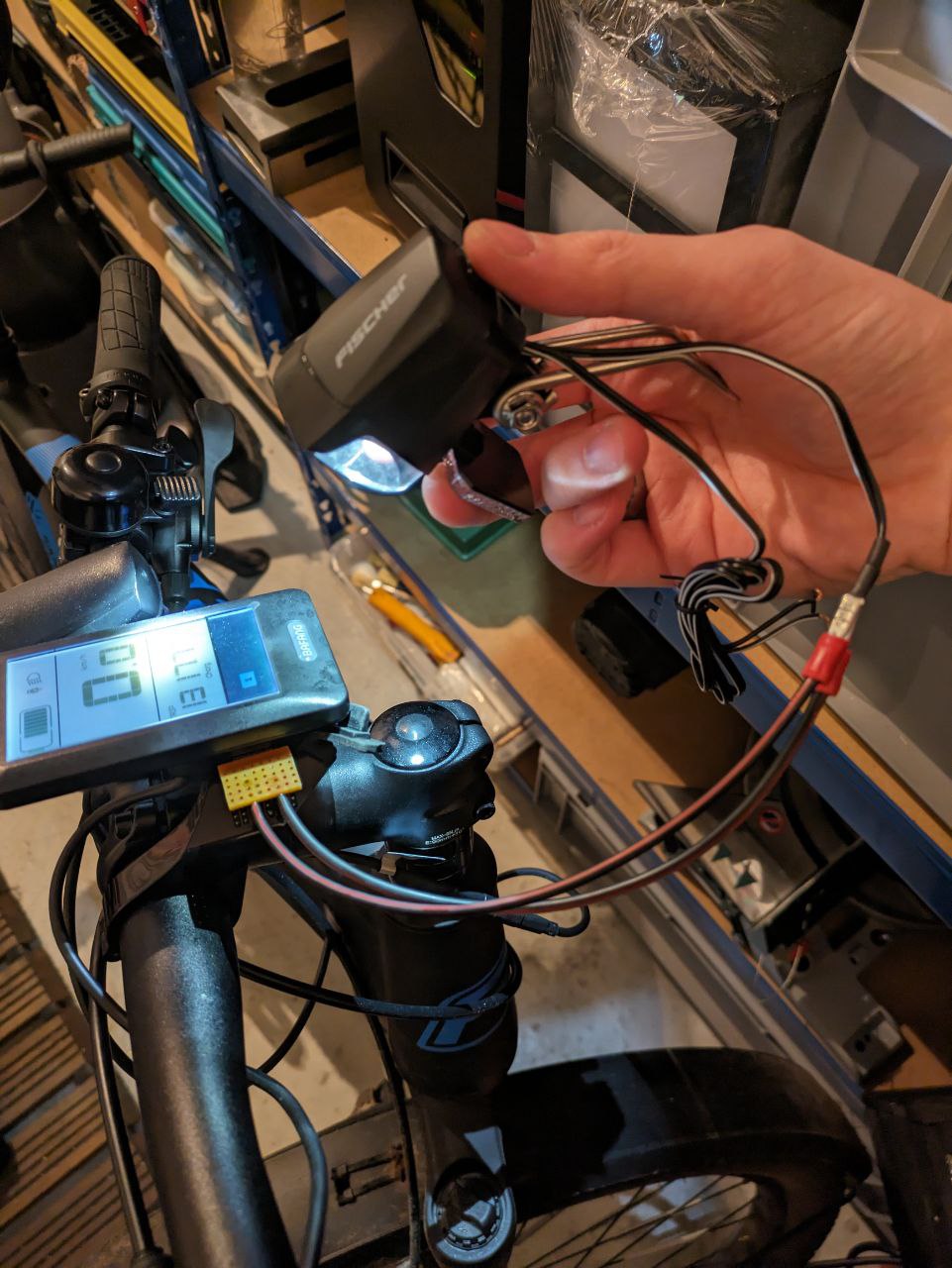
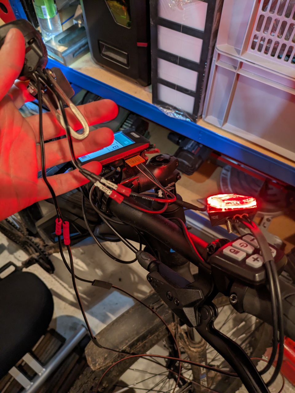
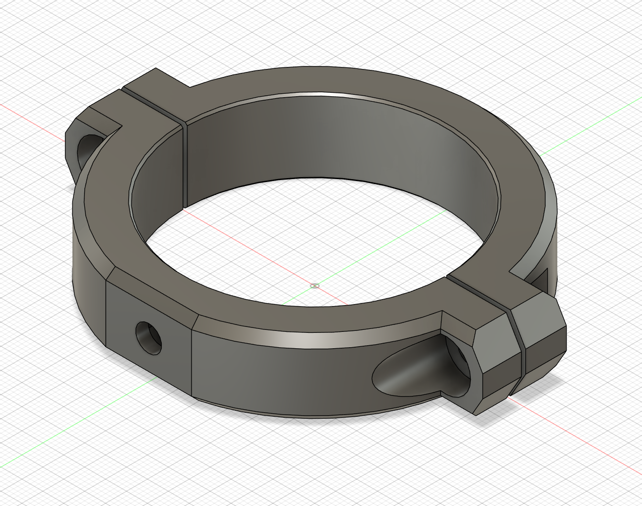
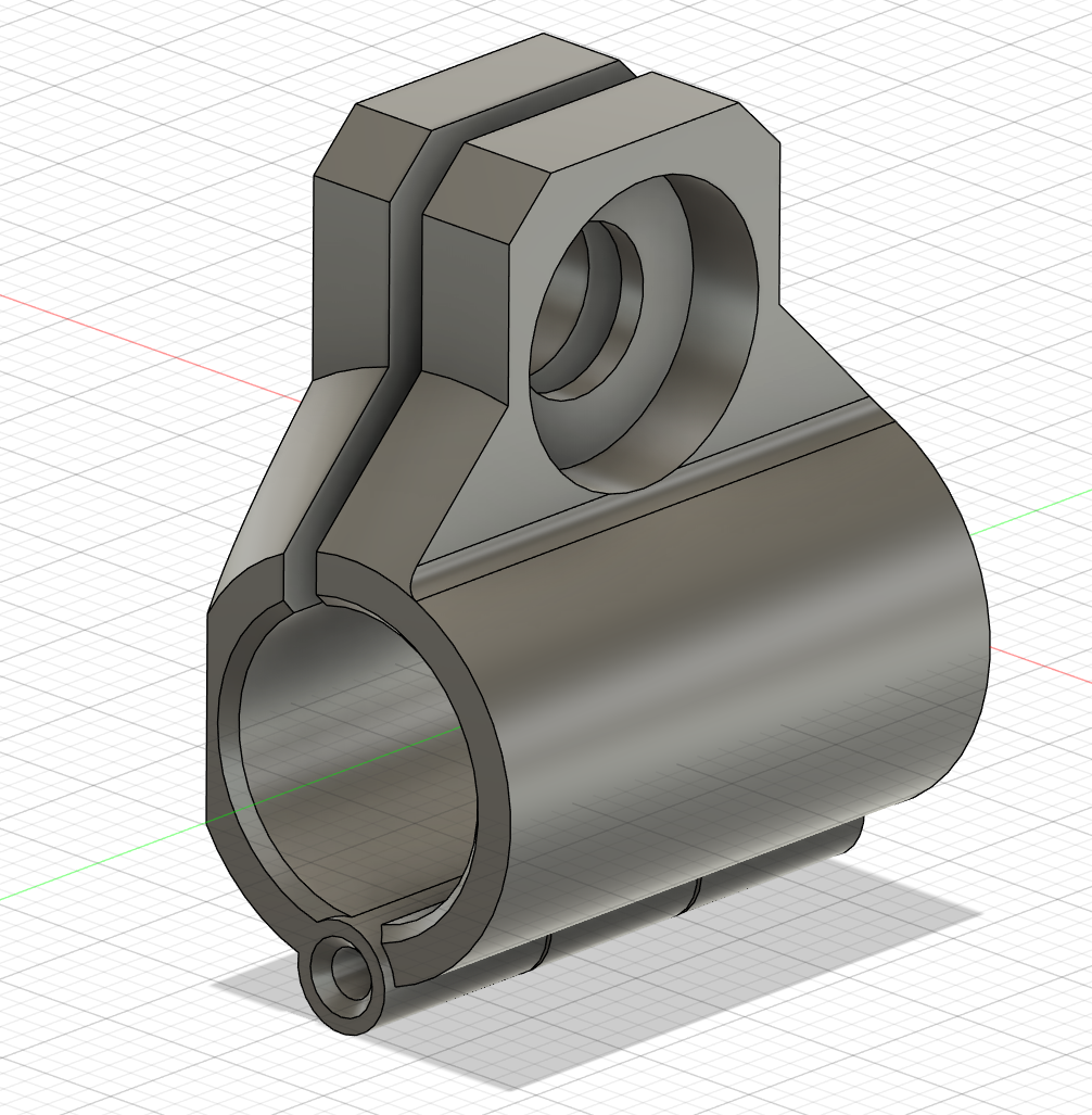
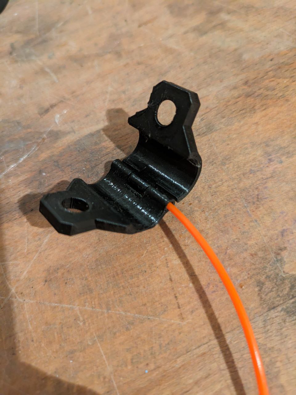
Now that the difficult part was done, all that had to be done was printing the remaining mounts and wire everything to the bike.
Update from Bike Carrier v2
After almost 2000 km there a no visible damages or deformation on the 3D printed PETG parts.
